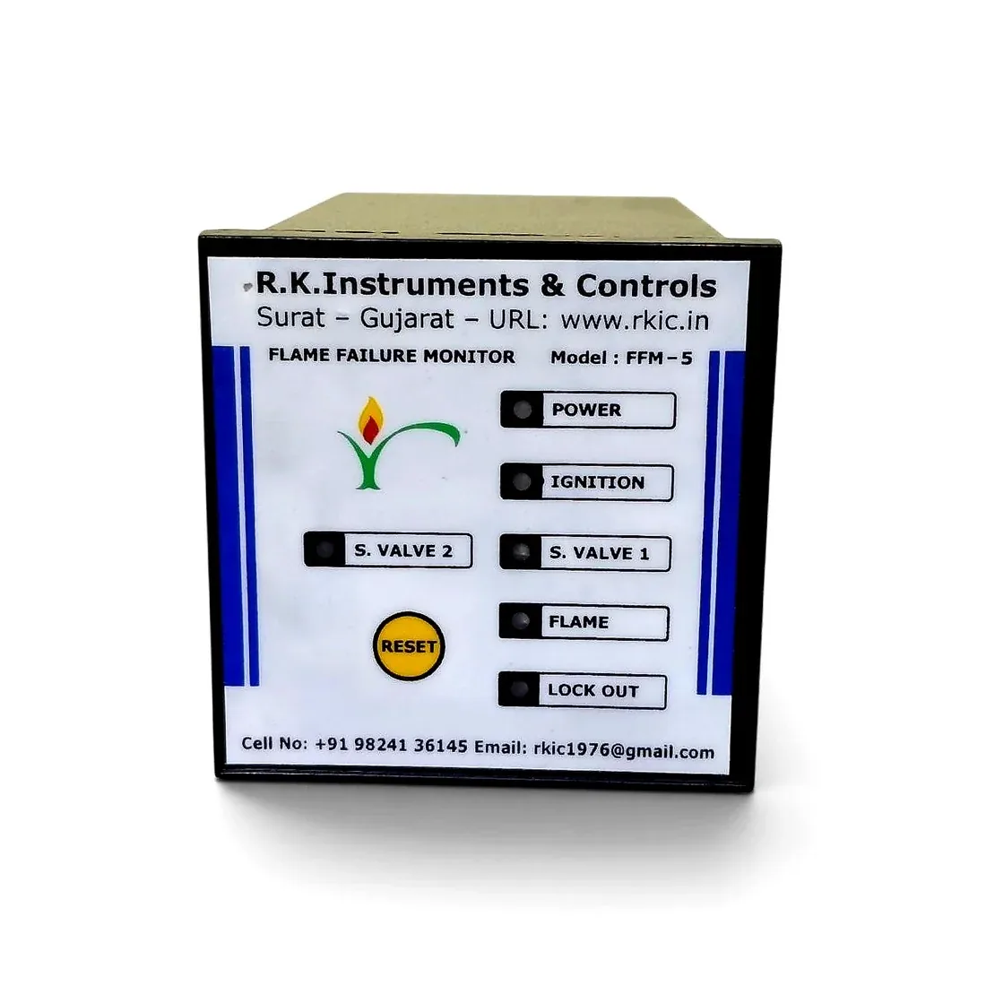

R.K. Instruments & Controls manufactures the FFM-5 Flame Failure Monitor, a flame-conduction (ionization) type burner safety controller for gas-fired furnaces, boilers, flare chimneys, special atmosphere furnaces and other industrial gas-fired equipment. Unlike optical/UV or infrared flame sensors, the FFM-5 senses flame by conduction current through a heavy-duty high-temperature sensing electrode rated to withstand up to 1200°C continuous operation, so it is unaffected by ambient room light, radiant furnace heat or soot accumulation. It automates a full pilot-and-main sequence: on power-up the POWER LED lights, and after a 3-5 second safety pre-delay the Ignition Transformer and Pilot Solenoid Valve (SV-1) energize together. Once flame touches the sensing rod, an ionization current confirms flame and the FLAME LED lights; ignition cuts off after 10-12 seconds while SV-1 stays energized, and 10-12 seconds later the Main Solenoid Valve (SV-2) energizes to bring the burner to full firing. If the pilot fails to establish within the 10-12 second ignition window, or flame is lost during running (with one 10-second automatic re-ignition attempt), the controller cuts all fuel valves and the ignition transformer, latches into Lock Out with its LOCK OUT LED and alarm/beacon output, and is restarted via the front-panel yellow RESET button or an external reset terminal. The rear panel carries an S1/S2 toggle to select the primary or backup flame sensor, a BYPASS toggle for offline bench-testing only (must remain in the Right/Normal position whenever gas lines are live), a dedicated protection fuse, and full terminal blocks for 230VAC supply, both flame sensor inputs, Ignition, SV-1 Pilot, SV-2 Main and Lock Out outputs, plus an auxiliary Main SV2 Extra contact. Suitable for multi-burner installations and dual-stage pilot/main firing sequences.
| Step | Action | Delay / Condition | Output / Status |
|---|---|---|---|
| 1 | Power ON | 230V AC supply applied | Controller powered; POWER LED ON |
| 2 | Ignition + SV-1 Pilot ON | 3 to 5 sec safety pre-delay after Power ON | Ignition Transformer & Pilot Solenoid Valve (SV-1) energize together; IGNITION & S. VALVE 1 LEDs ON |
| 3 | Flame Detection | As flame touches the sensing electrode | Ionization/conduction current confirms flame; FLAME LED ON |
| 4 | Ignition Cutoff | 10 to 12 sec after Ignition ON | Ignition Transformer OFF (IGNITION LED OFF); SV-1 Pilot remains energized |
| 5 | SV-2 Main ON | 10 to 12 sec overlap/stabilization after Ignition cutoff | Main Solenoid Valve (SV-2) energizes; S. VALVE 2 LED ON — full firing rate |
| 6 | Flameout Re-Ignition | If flame signal is lost during running | Ignition re-attempts for 10 seconds to re-establish pilot flame |
| 7 | Lock Out | Ignition fails within 10-12 sec at startup, or re-ignition fails within 10 sec during running | SV-1, SV-2 & Ignition cut off; LOCK OUT LED ON; alarm/beacon output active |
| 8 | Restart | Front-panel yellow RESET button, or external reset terminal | System restarts from Step 1 |
Note: Flame is sensed by conduction current through the high-temperature electrode (up to 1200°C), not by light or heat — ambient room light, furnace radiant heat and soot do not affect detection. All timings are approximate (3–5s pre-delay, 10–12s ignition/overlap windows) and factory-set; confirm exact values for your application.
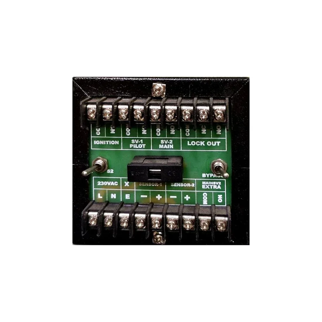
| Terminal / Control | Function |
|---|---|
| L / N / E | 230V AC supply input (Live / Neutral / Earth) |
| Sensor-1 (− / +) | Primary flame sensor (Sensor 1) input terminals |
| Sensor-2 (− / +) | Backup/auxiliary flame sensor (Sensor 2) input terminals, selected via the rear S1/S2 toggle |
| Ignition — COM / NO | Ignition Transformer output |
| SV-1 Pilot — COM / NO | Pilot Solenoid Valve output |
| SV-2 Main — COM / NO | Main Solenoid Valve output |
| Lock Out — COM / NC / NO | Lock Out / alarm & beacon output, potential-free changeover |
| Main SV2 Extra — COM / NO | Auxiliary potential-free contact, mirrors Main SV-2 status for remote PLC/annunciator signalling |
Safety Note: The rear BYPASS toggle must always remain in the Right (Normal) position during live operation. Setting it to Left bypasses the flame safety circuit for offline bench testing only — doing so with gas lines active is a severe fire/explosion hazard.






























We represent the sales & service of these manufacturers across our territories.

 Brahma
 Cofi
Cofi Danfoss
 Dungs
Dungs Elektrogas
 Honeywell Eclipse
 Honeywell Elster
 Honeywell Kromschröder
 Honeywell Maxon
 Honeywell Technologies
 Madas
Madas R.K. Instruments & Controls
 Siemens
 Vanaz
Vanaz